
Productscpzx

1. Product Overview
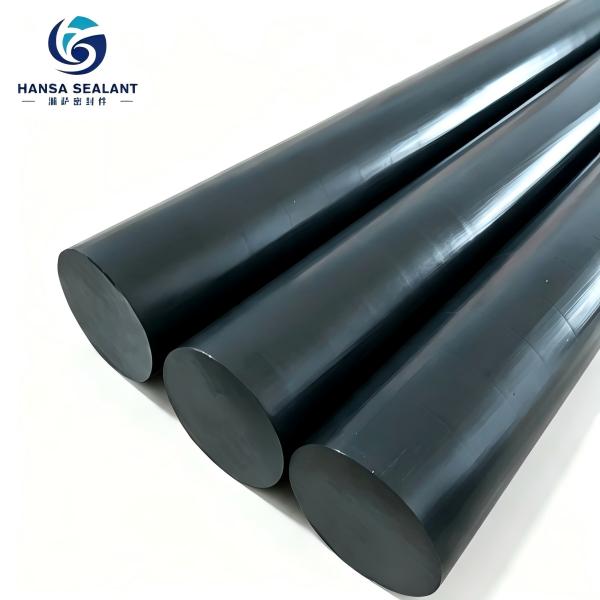
PTFE Graphite Rod is a high-performance composite rod manufactured by using polytetrafluoroethylene (PTFE, commonly known as the "King of Plastics") as the base resin, filled with a specified proportion of high-purity graphite powder, followed by mixing, compression molding, and high-temperature sintering.
Main Production Methods:
• Compression Molding & Sintering (Mainstream Process): PTFE suspension resin and graphite powder are uniformly mixed at high speed according to a specified ratio, loaded into a steel mold and pre-formed at room temperature under high pressure (typically 15–30 MPa). After demolding, the preform is sintered in a furnace at 360–380°C, followed by slow cooling to obtain a dense rod. This process is suitable for large-diameter and long-size rods.
• Isostatic Pressing: A rubber mold is used and the preform is compacted under high-pressure liquid medium, yielding better density uniformity. Suitable for large-specification and irregular-shaped rod blanks.
• Extrusion Molding: Suitable for continuous production of small-diameter, long-size rods with high efficiency, but the diameter range is limited.
Common graphite filling ratios include 15%, 20%, 25%, and 40%. Different ratios correspond to different mechanical, thermal, and wear-resistant properties to meet diverse operating conditions.
2. Product Properties
PTFE Graphite Rod combines the chemical inertness of PTFE with the self-lubricating and thermal-conductive properties of graphite. Its main physical and chemical properties are as follows:
| Property Category | Specific Parameter | Typical Value / Description |
| Density | Bulk Density | 1.7–2.1 g/cm3 (increases with graphite content) |
| Mechanical | Tensile Strength | 8–15 MPa |
| Elongation at Break | 50%–150% | |
| Compressive Strength | 15–25 MPa | |
| Shore Hardness (D) | 50–65 | |
| Thermal | Long-term Service Temp. | −200°C to +260°C |
| Short-term Service Temp. | Up to +280°C | |
| Thermal Conductivity | 0.5–1.2 W/(m·K) (significantly higher than pure PTFE) | |
| Coefficient of Linear Expansion | 8–12 × 10⁻⁵ /°C (lower than pure PTFE) | |
| Friction & Wear | Friction Coefficient | 0.08–0.15 (dry friction) |
| Wear Resistance | Several to dozens of times higher than pure PTFE | |
| Chemical | Chemical Corrosion Resistance | Resistant to nearly all acids, alkalis, and organic solvents, except molten alkali metals, fluorides, and a few solvents under high temperature and pressure |
| Weather Resistance | Excellent — UV-resistant and aging-resistant | |
| Non-stickiness | Extremely low surface energy; media do not easily adhere | |
| Electrical | Volume Resistivity | 108–1012 Ω·cm (changes from insulating to semi-conductive/anti-static after graphite filling) |
| Dielectric Constant | 2.5–3.5 | |
| Other | Water Absorption | < 0.01% |
| Flame Retardancy | UL94 V-0, self-extinguishing |
Core Advantages Summary: Compared with pure PTFE rod, PTFE Graphite Rod shows significant improvements in thermal conductivity, dimensional stability, creep resistance, and wear resistance, while retaining PTFE's outstanding chemical corrosion resistance and temperature tolerance.
3. Typical Application Fields
| Industry | Specific Application Scenarios | Typical Components |
| Chemical & Petroleum | Corrosive medium conveyance, reactor sealing, valve packing | Sealing rings, packing rings, valve seats, gaskets, linings |
| Machinery Manufacturing | Oil-free lubricating bearings, guide components, wear-resistant sliders | Bearing sleeves, guide rings, piston rings, wear strips |
| Food & Pharmaceutical | Hygienic conveyance, filling equipment sealing, aseptic environment components | Sealing rings, scrapers, guide wheels |
| Power & Electrical | High-voltage insulation, anti-static sealing, cable sheathing | Insulating gaskets, anti-static seals, cable accessories |
| Semiconductor & Electronics | High-purity chemical conveyance, wafer processing equipment | Corrosive fluid pipe fittings, seals, load-bearing components |
| Automotive & Transportation | Fuel systems, braking systems, high-temperature pipeline sealing | O-rings, oil seals, valve stem seals, bushings |
| Textile & Dyeing | High-temperature guide rollers, corrosion-resistant cloth guide rollers, tension rollers | Roller coatings, bearing bushings, seals |
| Aerospace | Sealing and structural components under extreme temperature environments | High-temperature sealing rings, self-lubricating bearings, insulators |
| Water Treatment & Environmenta | Dosing systems, corrosive medium pumps and valves | Pump seals, valve seats, diaphragms |
4. Selection & Design Guide
4.1 Basic Selection Principles
1. Temperature Matching: Long-term operating temperature should not exceed 260°C; transient temperature should not exceed 280°C. Low-temperature environments down to −200°C are acceptable.
2. Media Compatibility: Confirm that the working medium is not on the PTFE non-tolerant list (molten alkali metals, elemental fluorine, chlorine trifluoride, etc.).
3. Load and PV Value: For dynamic sealing/bearing applications, verify the PV value (pressure × linear velocity). Recommended PV value ≤ 3 MPa·m/s (dry friction); can be moderately increased with lubrication.
4. Conductivity Requirements: For anti-static or conductive applications, select a high graphite filling ratio (≥20%).
5. Dimensional Accuracy: Compression-molded rods generally have a tolerance of ±0.5 mm; after precision machining, tolerances can reach ±0.05 mm. Reserve machining allowance in design.
4.2 Common Models & Specifications
| Model | Graphite Content | Density (g/cm3) | Tensile Strength (MPa) | Application Scenarios |
| PTFE-G15 | 15% | 1.80–1.90 | 12–15 | General-purpose sealing, low-load bearings |
| PTFE-G20 | 20% | 1.85–1.95 | 10–13 | Medium-load wear resistance, thermal-conductive sealing |
| PTFE-G25 | 25% | 1.90–2.00 | 9–12 | High wear resistance, anti-static applications |
| PTFE-G40 | 40% | 2.00–2.10 | 8–10 | High thermal conductivity, high conductivity, heavy load |
4.3 Standard Size Specifications
| Diameter Range (mm) | Length (mm) | Molding Method | Tolerance (mm) |
| Φ6 –Φ30 | 100–300 | Compression / Extrusion | ±0.3 |
| Φ30 –Φ100 | 100–300 | Compression | ±0.5 |
| Φ100 –Φ200 | 100–250 | Compression | ±0.8 |
| Φ200 –Φ400 | 100–200 | Compression / Isostatic | ±1.5 |
Non-standard sizes can be customized. Rods can be machined by turning, milling, drilling, etc. into various seals, bushings, and custom-shaped parts.
4.4 Design Considerations
• Creep Compensation: PTFE-based materials exhibit cold flow tendency. When designing seal grooves, elastic compensation structures (such as V-type combined seals, spring-energized seals) are recommended.
• Clearance Control: When used as bearings or guide components, a fit clearance of 0.05–0.15 mm is recommended (depending on diameter and temperature) to prevent thermal expansion seizure.
• Surface Roughness: The mating surface roughness is recommended to be Ra ≤ 0.8 μm to reduce wear rate.
5. Usage & Maintenance
5.1 Installation Notes
• Clean mating surfaces before installation; avoid burrs and scratches that may cause seal failure.
• For interference-fit assembly, thermal assembly (heating to 80–120°C) is recommended; avoid forced hammering that may cause cracking or deformation.
• For threaded connections, use PTFE-specific sealing tape or compatible sealant; avoid sealants containing petroleum-based solvents.
5.2 Operation & Maintenance
• Regular Inspection: Dynamic seals should be inspected for wear every 3–6 months. Replace when wear exceeds 1/3 of the original thickness.
• Lubrication Management: PTFE Graphite Rod is inherently self-lubricating; no additional lubrication is required in dry-friction conditions. Clean lubricating media, if available, can significantly extend service life.
• Temperature Monitoring: Monitor friction surface temperature during long-term operation. Reduce load or stop for inspection when temperature exceeds 260°C.
• Media Purity: Prevent hard particles from entering the friction pair — abrasive particles can drastically accelerate wear.
5.3 Storage Requirements
• Store in a cool, dry place, away from direct sunlight and high-temperature environments.
• Keep away from sharp objects to prevent surface scratches.
• Store large-diameter rods horizontally; long-term vertical storage may cause bending deformation.
• Shelf life is generally 5 years. Re-test mechanical properties before use after expiration.
6. Development Trends
6.1 Advanced Material Compositing
• Multi-component Filling Systems: Combining graphite with carbon fiber, glass fiber, bronze powder, molybdenum disulfide, etc. to achieve synergistic optimization of wear resistance, thermal conductivity, and mechanical properties. For example, a graphite + carbon fiber combination can simultaneously improve wear resistance and dimensional stability.
• Nano-modification: Introducing nano-graphite flakes, graphene, and other nano-fillers to achieve significant improvements in thermal conductivity and mechanical properties at low loading levels — a current research hotspot.
6.2 Process Refinement
• Large-diameter Continuous Extrusion: Breaking through the diameter limitations of traditional extrusion processes to achieve continuous, efficient production of medium-to-large diameter rods.
• 3D Printing / Additive Manufacturing: Additive manufacturing technology for PTFE-based composites is maturing, enabling near-net-shape forming of complex structural parts and reducing material waste.
• Surface Modification: Sodium treatment, plasma treatment, and other methods improve the surface adhesion of PTFE Graphite Rod, expanding composite applications with metals.
6.3 Green & Sustainable
• Recycling & Reuse: Technologies for pyrolysis recovery and grinding-and-refilling of PTFE waste continue to advance, reducing the environmental impact across the full life cycle.
• Low-VOC Production: Promoting solvent-free, low-emission molding processes to comply with increasingly stringent environmental regulations.
6.4 High-end Application Expansion
• Semiconductor High-purity Grade: Ultra-high-purity PTFE Graphite Rod meets the stringent requirements (ppb level) for metal ion leaching in semiconductor manufacturing.
• New Energy Sector: Adapting to corrosion resistance, temperature tolerance, and insulation needs in emerging industries such as hydrogen energy, energy storage, and photovoltaics.
7. Market Application Expansion
7.1 Hydrogen Energy Industry
In hydrogen energy equipment, electrolyzers, hydrogen refueling stations, and hydrogen fuel cell systems have extensive requirements for high-pressure hydrogen sealing and corrosion resistance. PTFE Graphite Rod, with its hydrogen embrittlement resistance, temperature tolerance, and self-lubricating properties, can be used for hydrogen sealing rings, valve seats, insulating bushings, and other components. The market space is growing rapidly with the construction of hydrogen energy infrastructure.
7.2 Semiconductor Manufacturing
Semiconductor wafer processing involves a large number of highly corrosive chemicals (hydrofluoric acid, aqua regia, organic solvents, etc.) and ultrapure water systems. Seals, pipe fittings, and load-bearing components made of high-purity PTFE Graphite Rod are key consumables in CMP, etching, and cleaning equipment, with strong demand for domestic substitution.
7.3 New Energy Vehicles
Electric drive systems, thermal management systems, and high-voltage connection systems in new energy vehicles impose higher requirements on the temperature resistance, media resistance, and insulation performance of seals. PTFE Graphite Rod can be used for motor insulation rings, battery pack sealing, high-voltage connector sealing, etc., with per-vehicle usage continuously increasing.
7.4 Photovoltaics & Energy Storage
Heat dissipation and sealing components in photovoltaic inverters and energy storage converters, as well as corrosion-resistant electrode frames and sealing structures in flow batteries, provide new incremental markets for PTFE Graphite Rod. Its combined characteristics of thermal conductivity + insulation + corrosion resistance are irreplaceable in these scenarios.
7.5 Medical & Life Sciences
Micro seals and guide components in high-end medical devices (such as analytical instruments, infusion pumps, heart-lung machines) require biocompatibility and resistance to repeated sterilization. FDA-compliant PTFE Graphite Rod continues to deepen its applications in this field.
8. Conclusion
As a classic category of PTFE-based composites, PTFE Graphite Rod achieves key enhancements over pure PTFE in thermal conductivity, wear resistance, creep resistance, and dimensional stability through graphite filling, while fully retaining PTFE's core advantages of chemical corrosion resistance, high/low temperature tolerance, non-stickiness, and adjustable insulation/anti-static properties. It is an indispensable high-performance engineering material in industries such as chemicals, machinery, electronics, and energy.
Looking ahead, with the continuous advancement of material compositing, process refinement, and high-end application expansion, PTFE Graphite Rod will find broader application space in strategic emerging industries such as hydrogen energy, semiconductors, new energy vehicles, and photovoltaic energy storage. For end users, rational selection, standardized installation, and regular maintenance are the keys to fully unlocking the performance potential of PTFE Graphite Rod and extending its service life. We recommend engaging with the material supplier for technical alignment at the early project stage to customize the optimal material formulation and dimensional solution based on specific operating condition parameters.


